CLASS EXERCISES AND PROJECTS
PROJECT 4
DATE: 12/10/2017
Problem statement: Modeling a robot in Maya using different modeling tools and techniques.
For this project, I wanted to model some complex robot. This project comes under advanced modeling focus area. So for modeling robot, I found one image of robot named Mr. Steel. (source link :https://d1sk1ss.deviantart.com/art/mr-Steel-85623791) This Mr. Steel robot looks like really challenging to model in Maya as I found only one reference image. So I decided to start modeling this robot using one reference image. In this project first I created rough robot like model using NURBS sphere, cylinder etc. I started modeling each part like legs, hands etc. and adjusted vertices of NURBS to give desire shape. I model this reference base model of robot with reference of Mr. Steel image. My approach was to build curve shield like structures of robot with reference of base model using quad draw tool as it would be really difficult to model curve shield structures of robot body in air without reference model and images (side view, front view, top view etc.).
Once base reference model get build, I converted all NURBS to polygons and combine the all polygons to make one single base model. Then I start modeling actual robot. I start with left leg of robot. First I make robot base model surface live so that I can draw quads. Then I draw quads on surface of base model, in this process I also referred the reference image of Mr. Steel. Once quads get draw, I adjusted it’s vertices to make it looks like body shield of actual Mr. Steel robot. Like this step by step I created all shields of left leg of robot. Then I used extrude tool to make shield thick and also used the multi cut and insert edge loop tools to adjust the edges of shields. Once shield part finished, I started working on its internal structure. So for this I created different mechanical parts. The connection rods created using polygon cylinder and extrude and insert edge loop tools. Like this I created other different parts like circuit blocks, circuit shield. I first adjusted the circuit base inside left leg structure then front side rods and then place and adjusted the other circuit’s blocks on the top of circuit base. I then modeled the front and side foots with the same procedure which I followed for modeling shields. The foot’s circuits, mechanical parts modeled using the polygon cube, sphere, cylinder and tools like insert edge loop, mirror, extrude etc.
Once left leg modeling finished, I started working on left hand part. So first I created the shoulder shield using quad draw technique and adjusted the vertices with reference of base mode and image. I used the insert edge loop, extrude, multi cut tools to make the shoulder looks like shoulder of actual robot. Then I created the hand shield with same procedure. I created the fingers and adjusted each block of fingers. I then used the robot accessories (mechanical parts like rods) which I created. I duplicate them and adjusted between hand and left shoulder. I also created small wheel like fan with multiple blades and ring around it. And copied this and adjusted into hand and leg.
Once the left hand modeling finished, I started working on middle part (main center body) of robot. Using the quad draw technique, I modeled the different shields of middle part of robot. I adjusted the vertices of quads and used insert edge loop, multi cut, extrude, and snap to grid etc. tools to give the shields the actual shape as per the robot model in the image. The front light lamp created using polygon cylinder and tools. After that I created inner part of main body of robot using cylinder and tools. After finishing the modeling the middle main body part, I modeled the upper head shield using quad draw technique and adjusted the vertices of quads to give it desire shape. I modeled the head using sphere polygon and different tools to give it desire shape.
I then start working on right hand of robot, the right hand structure is different than left hand, So I modeled the right hand separately. First I created shoulder shield and then modeled the hand shield structure. I then modeled the inner structure of hand and shoulder and inserted the connector rods between hand and shoulder. I make copy of left hand fingers and used this for right hand by adjusting their position. I also created joint bolts and place them between two blocks of each finger. For the right leg I make the copy of left leg and used this copy as right leg as both legs looks similar as per the robot in image. At the end I modeled the upper receiver kind structure using different tools and adjusted the structure on top left of robot.
Once modeling get finished I started working on shading and texturing part. I used phong shader and apply it on different parts of robot. After shading, I created three spot light and adjusted them on top of robot. I also used one spot light and place it inside the front light of robot and enable fog feature of light. Once the light setting completed, I created camera and animate the camera in such a way that it focuses on main parts of robot. After animation I rendered the animation and created video of animation and uploaded below. I also created rendered frames from animation and uploaded below in another section.
Link of maya file: https://drive.google.com/open?id=1jONFsB5BDhVBUlfIzru3yutW2Owea3KO
Link of animation video: https://drive.google.com/open?id=1xnL7JEcJuo86duL0yoQR8wXChPAsj_KY
Link of reference image: https://drive.google.com/open?id=1jSPvc1k_WLyn8HDzYuyBZ5BzoTwRs3ff
ANIMATION VIDEO
RENDERED FRAMES OF ANIMATION


CLASS EXERCISE 15
Problem statement: Shading an axe
For this exercise of shading the axe, first I created model of axe using cylinder and cube polygon primitives. After finishing the model of axe, I started working on shading the axe, first I select metal axe head and assign phong material to it. I adjusted the colour to light blue gray of phong to look like metal and changed the specular attribute to get desire brightness on the metal surface. I then changed the cosine power of phong to increase the spread of specular highlights. Then mapped the environment chrome to metal’s shader’s reflected colour attribute as this environment chrome texture provides an interesting reflection. Adjusted the environment chrome’s placement node to centre of metal. Then I started shading the handle of axe. For this I assign phong material, adjusted it’s specular colour and cosine power attributes. Then mapped the wooden texture to phong’s colour attribute and adjusted the Filler colour, Vein colour attributes of wooden texture to make it looks like real wood. Scaled the placement node of wooden texture around axe handle.
To make the top part of handle metallic, I used layered shaders. For this first I selected the handle of axe and assign layered shader material to it. Then to make layers of wood and metal (at top of handle), in Hypershade, I drag the wood material into layer shaders attribute editor window. I deleted the default green shader. Then I drag the metal material into the same. Then created ramp texture and mapped it to colour attribute of wood material. Then in ramp’s attribute editor, changed interpolation to none and selected type to V ramp. Then adjusted the white colour of ramp to adjust the wooden layer and metallic layer on axe handle. At the end I rendered out the frame of axe and added these frames below.


PROJECT 3: RIGGING
DATE: 11/13/2017
Problem statement: Creating animation rig for an alien.
Solution description:
For this project of creating rig for an alien, the alien model was provided as starting point of this project. The model didn’t had skeleton which is required for creating rigs. So first I created skeleton using HumanIK tool in Maya . Here initially the skeleton was not properly adjusted and for alien, I added joints to basic skeleton like joints in foot, spine, back part of head, joints for eyes. Once this process completed, I adjusted the complete skeleton into alien body in which primarily I adjusted joints of each finger of both hands of alien. After this process, I bind the skin to skeleton using bind skin tool. And then I started creating rigs. In this rigging process I started creating basic root rig control which controls complete alien. Then I created rigs for pelvis, waist, spines, chest. Here I used orient constraint between respective bone (joint) and control rig. Then I created hierarchy between these joints like. I made waist rig child of pelvis rig. And then made root rig parent of these rigs. After that I added rig for hands and used IK handle tool to add IK chain between arm joint and wrist joint of hands. I applied constraint between IK chain and control rig of wrist so that wrist control rig can control complete hand using IK chain. I also created pole vectors for hand IKs and applied pole vector constraint between pole vector and ik chain. I did not make these wrist rigs child of chest rig, but I made it child of root rig.
For fingers, I used set driven key technique in which first I added attributes to wrist control for each finger. Here I set minimum to -10 and maximum to 30 and default to 0. then using set key option, I selected wrist control as driver and finger joint as driven. I set value in attribute to 0 and set key then again set value of attribute to -10 and rotate finger and set key. Like this I set keys for all fingers.
Then I created rig for neck, head, back par of head where I added couple of rigs. Again, I created hierarchy between these rigs and applied orient constraint between rig and respective joint. For the eyes, I face some difficulties while rigging eyes. I separated eyes and eyelids from alien mesh using separate command. Then I used to bind it with eyes joints using bind skin tool. I also adjusted each joint of eye to centre of respective eye. I created rigs for both eyes and then created one rig around them which is parent rig of both. I applied aim constraint between rigs and respective eyes joints.
At the end I created rigs for both legs and using the same way I applied constraints and created hierarchy between rigs.
Once rigging process finished, I created this rigging demo video and uploaded here below.
For the animation, first I created environment where on plane there are many obstacles and I used shaders and bump mapping to map texture on plane and obstacles. I also used spots lights for lighting the environment. Once environment created, I animate the alien in which I used control rigs for rotation, translation of body parts of alien. I generated keys for rig controls in graph editor of animation. In this animation, alien start walking and then running and once it sees obstacles alien jumps over obstacle and falls and again get up. After animation finished, I created rendered
video of animation using batch render tool and uploaded video below in different section. I also added frames of render of animation here below.
Link for Maya file: https://drive.google.com/open?id=1N2b6eLMDg0-0zU9zMs6sDgXVQnvaf3JT
Link for the rig demo video: https://drive.google.com/open?id=14_cNTMAf_Qugxh1cZF2MjA4Cupdo2VUJ
Link for the animation rig video :https://drive.google.com/open?id=1FFA9l_szfbi7fSPalB-Yv9LYhuG1bXiP
VIDEO OF ANIMATION RIG
RENDERED FRAMES OF ANIMATION RIG


CLASS EXERCISE 13
Watching Rigging tutorial on Pluralsight and describe three techniques or tools from tutorial
Solution: I watched tutorial "Introduction to Rigging in Maya 2017" on Pluralsight and I learnt many new techniques in rigging and tools as well. I found following three techniques more interesting and useful among all techniques. I add description of each technique and snapshots in following three sections.
1.
Controlling eyes using IK handles :
I found this technique of controlling eyes using IK handles effective and interesting. The instructor first duplicated the left eye and right eye joints and then parent them to respective eyes joints. Then he added IK handles to newly extended eyes joints and used orient constraint between these handles and their pivots. So the main use of this is to synchronize the rotation movement of both eyes. After that instructor added the control rigs around child joints of eyes joints and added one root control around both controls. So when he translate the root control, the eyes did not translate from their original position.


2. Spine IK handle tool:
In the tutorial, instructor used this spine IK handle tool for creating IK handles for spine joints structure. This tool located under skeleton menu : skeleton -> Create IK spine handle. In this tool setting options, instructor selected Root on curve and auto create curve options and created spine IK handle and then he grouped the curve and IK handle. This tool is important in the animation process of spine. This IK handles for spine can make animation process easy and less time consuming. We can bind control rig to spine and this control rig rotation represent the animation of spine effectively and smoothly.


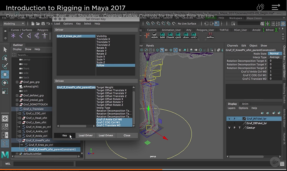
3. Creating follow controls for knee pole vectors:
In this technique, to follow the foot by knee pole vector which are controlling knee, instructor first created attribute follow for knee pole vectors and edit these attributes so that these knee pole vectors will follow the foot controls. He also used set driven key for knee pivot control and knee pivot offset parent constraints.


CLASS EXERCISE 12
Problem statement: walk cycle animation for Block_man using forward kinematics and Inverse kinematics
Solution description:
In this exercise, we provided the block_man model as starting point of this exercise. I started this exercise by creating skeleton (joints) for complete body of block man. Once all joints created, I created hierarchy like for each joint corresponds to body part, I made that body part child of respective joint. I created walk cycle by using forward kinematics, here I represent the nervous and rushed style in animation of block man walk cycle and I followed steps:
1. At starting, I generated key frames for all joints in hierarchy at frame 0. Then I rotate joints at 5 interval frames in graph editor to create walk cycle animation. At each frame (1,5,10,15,20,25,30) I generated key frames after rotation of joints. Like this, I created first walk cycle.
2. Then I use the key frames from first cycle for making some loops of walk cycle.
3. Then I run the animation and removed monotony in walk cycle loops by adjusting key frames.
Next, I created walk cycle animation using Inverse kinematics, here for this walk cycle I represent the nervous style and followed steps:
1. First, I created IK handles for both legs and foots of block_man model using IK handle tool.
2. For animating legs and foot, I used these IK handles and I animated upper body in the way I animated in forward kinematics method.
4. At each frame (1,5,10,15,20,25,30 ) I generated key frames after rotation of joints and IK handles. Like this, I created first walk cycle.
3. I used the ky frames from first cycle to create loops of walk cycle animation. I removed monotony in animation by adjusting key frames.
At the end, I created videos of both animations using play blast tool. And uploaded these videos below.
First video is of Forward kinematics and 2nd video is of inverse kinematics
WALK CYCLE USING INVERSE KINEMATICS
PROJECT 2
Problem statement:
Shading, Lighting, Texturing, Rendering, animating a Unicycle
Date: 10/23/2017
Solution description:
1. About unicycle animation theme (idea) : For this project of animation , texturing, lighting of unicycle, I decided to implement the animation of unicycle in the some unique environment where most of animation principles can be apply. So for this unicycle animation, I created curve like surface and make it smooth by adding multiple edge loops and adjusted them. The middle part of curve path/surface supported by two pillars. The unicycle start running from middle top surface. It goes till end of flat part and again comes back then it again get ready for going ahead. Here the animation principle I used is anticipation. Once it reach to the curve part then it start moving further slowly and then it catches the speed as it moves towards bottom flat surface. Here the principle of animation used is slow in. Like way with the speed unicycle reaches the next top part of curve surface. Because of motion and speed it goes beyond the upper edge of curve surface and it rotates in air twice and comes back to upper ground surface. Here the two principle of animation used: exaggeration and squash and stretch. Unicycle again comes down through curve surface and tries to go to next upper surface but because of some less speed it can't. Again it comes to bottom survace and thinks about how to go up and it inspires itself and get ready to go up on next surface. It start running and grabs speed and reaches to top sufrace. Again it get ready to reach actual target. The target is curcular culindricl surface somewhat far from end curve upper edge. Again unicycle starts running and as it reaches the start of curve and start running slowly and catch speed as it goes down and with this speed it move towards the end of next curve surface. Because of speed it gains, unicyclestart flying in air and reaches the destination target. The priciples of animation apply is anticipation and squash and stretch.
Implementation details:
1. First I created environment. Then I started animating the unicycle. For this first I created three NURBS curves for seat part, middle part and for complete unicycle. I created hierarchy of these curves like main control root curve make parents of other two curves. I applied orient constraints between seat group cur and seat group. I applied parent constraint between root control curve and unicycle group. For the animation of unicycle then I generated key frames for NURBS root curve which basically controls whole unicycle. Also simultaneously I generated key frames for wheel rotation and handle rotation according to animation direction.
Principles of animation applied:
1. Staging: I set camera which focus on unicycle.
2. Anticipation. The unicycle at starting, goes some distance and again comes back.
3. . Exgageration: Unicycle rotates twice in air.
4. Squash and stretch: When unicycle jumps on surfaces it get squash and at next moment it get stretch.
5. Slow in: Unicycle start it's running slowly at start if curve surface when it moves downward direction.
At the end I created video of animation and uploaded here below.
Link to maya file of project:
https://drive.google.com/open?id=0ByACdvkSx-3rcHg4Wm9MNnZSdkE
Link for animation video:
https://drive.google.com/open?id=0ByACdvkSx-3rdjRpYmpiaEU1N0k
RENDERED FRAMES FROM ANIMATION OF UNICYCLE


CLASS EXERCISE 11
Problem statement: Animating the throwing axe using key frame setting and editing
Solution description: For this exercise of animating the throwing axe, the models of axe and target were provided as starting point. First I grouped the all parts of axe and adjusted the pivot. In the same way I grouped the parts of target and adjusted it's pivot. To animate the axe i.e throwing towards target, I followed steps:
1. For rotation and forward motion of axe, I selected translate x, translate y and rotate z attributes of axe to set key frames on animation graph editor.
2. first at point 0 on graph editor, I set these three attributes and set key frame by using s key.
3. Then I rotated the axe around z axis in anticlockwise direction
4. Then I rotated the axe around z axis in clockwise direction and translate it around x axis and also little bit translated it around y axis.
5. In the same way I created 4 rotations of axe between it's starting point and target hitting point.
6. When it hits the target, I animate the axe to make it's movements realistic. And also I animated the target. Here I rotated target around z axis littlie bit and set key frames accordingly.
7. To make animation smooth, I adjusted key frames points on graph editor.
8. I created video of this animation using playblast tool.


CLASS EXERCISE 10
Problem statement: Finding principles of animation in movie and explaining the principles.
Solution description: For this exercise of observing the principles of animation in movie, I observed following principles of animation in movie: 'Toy Story' while watching the movie.
1. Staging
2. Squash and stretch
3. Arcs
4. Slow In
5. Exaggeration
6. Anticipation
I included the scenes from movie Toy story where I observed the principles of animation. I also described the application of principle of animation in each scene as follows:
1. Staging:
In the following scene of Toy story, the principle of animation used is staging as woody standing in front of all other toys and discussing the plan. Here Woody being the centre of attention of toys crowd. In the most parts of the scene viewer can observe the staging principle from view angle.
Squash and stretch
There's a very subtle use of squash and stretch in "Toy Story". Squash and stretch is often seen in scenes where the toys land onto a surface. Here in the following scene, the solders toys are landing from stairs to floor with parachute, the principle of animation squash and stretch is used to show the change of motion and body language of solders after their landing on floor.
Squash and stretch
Here I observed the squash and stretch principle in following scene in which the Buzz Lightyear following the running car and when he jumps into car his body language get changed and that indicates the squash and stretch principle.
Arcs
In this principle of animation, the position of hands, head, or body changed with motion in such way and in direction that looks like arc structure. In the following scene, the Buzz showing his flying power to all other toys and when he jumps on the ball, he bounce back in the direction with motion in such way that it looks like arc structure.
Exaggeration
In the exaggeration principle, the realistic movements of objects in animation included. In the following scene , the Buzz teaching Rex, when rex throws air from mouth, Mr. Potato head get affected badly and the effect of air animated in such way that it looks realistic effect.
Slow In
In the following scene the Buzz is flying and while flying he gets onto one vehicle toy.The start up of the scene is achieved when Buzz lands on the toy car when due to gravity slowly rides it down gaining more speed later in the decent.
CLASS EXERCISE 9
Problem statement: Create a turntable of the still life scene
Solution description: For this exercise of creating turntable of the still life scene, first I created plane, models of an egg, orange, wooden ball, tomato. For adding texture to orange, I used phong and added orange colour on it, to make it looks like real, I added noise texture on it. For egg, I used lambert shade and white texture on it. For wooden ball, I used lambert shade and wooden 3D texture on it, then I adjusted the attributes of wooden texture to create real shades on it. And for tomato, I used anisotropic shade and light red colour texture on it. For plane, I used phong shade and cloth texture.
Then I added three spot lights to scene and adjusted their angle and position to create three point light. And finally I create turntable from visualize menu of animation mode. I set number of frames 200.
I also rendered the scene and added rendered image of scene below video on web page.
I used Maya software renderer to create render video.


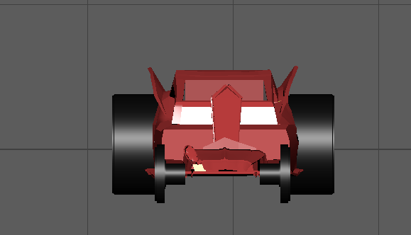
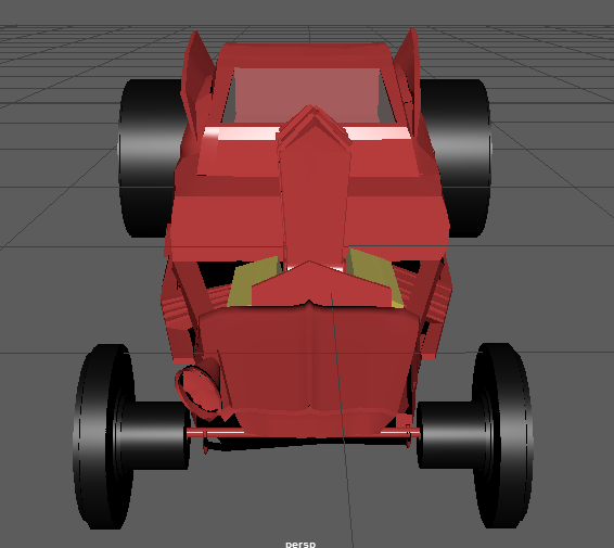
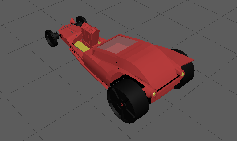
PROJECT 1
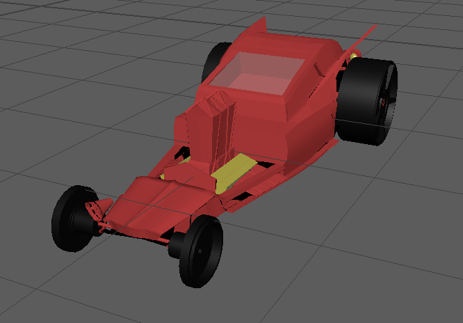
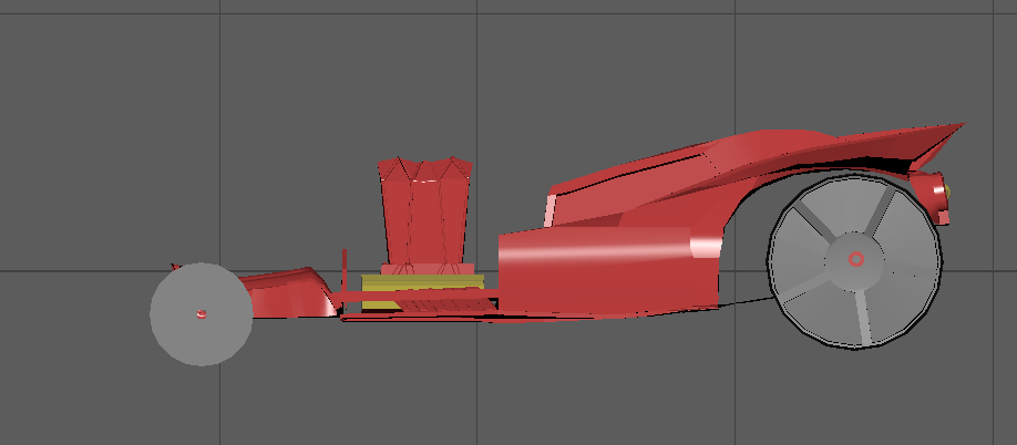
Title (Problem Statement): Modeling an object (Car) using primitives
Date: 10/04/2017
Solution description: In this project of modelling an object using different primitives like polygon primitives, NURBS primitives etc. I modelled a car (racing car). For modelling car, I used polygon primitives : cube, cylinders, pipe, sphere, torus etc. for modelling different parts of car.
I followed the following steps/procedure for modelling car.
1. First I captured some pictures of car model through different angles: side, top, back, front etc. I referred these pictures in modelling car. I created 3 image planes and imported side, top, front view images of car in these image planes in maya.
2. Then I created polygon cube as basic body of car. Then I inserted multiple edge loops using insert edge loops tool. I also used multi cut tool for inserting small edges .
3. To create top part of car (Window, sitting area, bonnet), I adjusted control vertices, faces and edges of particular area of cube.
4. To make top part sitting area of car, I used extrude tool, I extruded surfaces and created box after that I cover this box by making window. I created window by creating surface on top by extruding one edge and then adjusted vertices.
5. To create side wing like structure, I extruded side edges to top curve surface and then adjusted it's vertices to make it look like real structure, then I make it little thick.
6. To create back part of car and lights, I created 2 torus and make their shape looks like back lights using lattice deformer . Then I connected them by extruding their edges, Finally I attached this structure to back part of car.
7. To create middle part of car, I used extrude tool, I extruded surface and make cubic structure then I insert edge loops and adjusted vertices and edges to make this structure looks like real structure. To smooth the edges, I used bevel tool.
8. Front part of car created using insert edge loops,extrude tool, adjusting edges , vertices.
9. The front side light of car created using cylinder and then attached it to main car body model.
10.Bottom part of car is a plane which is created by extrude tool.
11. Tyres of car created by polygon cylinder. I created the front and back tyres separately. For the tyres, I used extrude tool, I extruded surfaces of cylinder.
12. To connect these wheels together, I created pipe and attached the pipe to main car model. Then Attached Tyres to it. Like this, I attached front and back tyres to main car body.
13. After completing the whole model of car, I coloured the whole car. Some parts of car like tyres, middle engine part, back light part coloured in different colour.
Link to maya file:
https://drive.google.com/open?id=0ByACdvkSx-3rdG1vLWN5a3FGRUE
Link to car model https://drive.google.com/open?id=0ByACdvkSx-3rS2haTUNaOG5hMzQ


CLASS EXERCISE 8
Problem statement: Animate flying text with use of different deformers
Solution Description:In this exercise of animating flying text, I used three different deformers : flare, twist, wave. First I created text then created first deformer twist. To animate the text, I set key frames on different time scale on animation graph editor. Again I created another two deformers : flare and wave and follow the same procedure of key frame setting to animate text.


CLASS EXERCISE 7
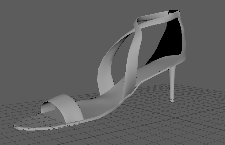
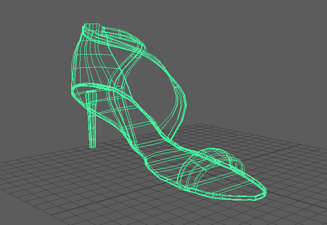
Problem statement: Modeling shoe using NURBS primitives.
Solution Description:In this exercise of modelling a shoe ,first I created base surface of shoe using cu curves and loft tool. Then to make it looks like real shape, I adjusted control vertices . I used NURBS cylinder to create three belts of shoe. Here I adjusted control vertices of bend cylinder to make belts , I also inserted multiple isoparms for curving and bending purpose. For making back supporting curve surface, I first created four cv curves and then used loft tool to make surface from curves. Then I inserted multiple isoparms and adjusted control vertices to make this shape like real shape. For bottom hill of shoe, I used NURBS cylinder. And final shoe model created.


CLASS EXERCISE 6
Problem statement: Modeling Pear using NURBS primitives.
Solution Description:In this exercise of modelling a pear , first I created NURBS sphere. Then to create lower part of pear, I inserted multiple isoparms and then adjusted isoparms by selecting their control vertices. In the same way I created upper part of pear. To create stems, I created NURBS cylinders and adjusted their control vertices to make real shape of stems. To create leaf of pear, I used plane NURBS primitive. I inserted multiple isoparms to it and adjusted each corner edge control vertices to make this plane shape looks like leaf. And final complete pear model get created.


CLASS EXERCISE 5
Problem statement: Modeling solar panel with help of Pluralsight tutorial :'in Creative Professional:Quick Start to Modeling in Maya: Volume 1'.
Solution Description:In this exercise of modelling a solar pan with help of pluralsight tutorial :in Creative Professional:Quick Start to Modeling in Maya: Volume 1, first I created single solar cell with help of cylinder polygon primitive and cylinder NURBS primitive. I created hexagonal shape of solar cell by using extrude tool. Then inserted each NURBS cylinder on base of cell and final solar cell created. Then I group both of cylinders and copy this group to make multiple solar cells. Then I created base of the panel body using cube polygon primitive. The edges of panel body make smooth and curve by using bevel tool and extrude tool. Then I adjusted the group of solar cells so that they can fit on base of solar panel body. Then I created bottom part of panel body. Once complete solar panel get created, I group all together and duplicated them to create other two solar panel. I rotated side panels.
Then I created array base using cylinder polygon primitive and extrude, insert edge loop tool, offset edge loop tool and bevel tools.
I created bracket using pipe polygon primitive . Here The radius , height and width of pipe adjusted. Here to the complete bracket get constructed using extrude tool, smooth tool, Once bracket get constructed, I adjusted it with array base and fit it into array base. So finally solar panel, bracket and array base get fit together.
Then I created base of legs of solar model using curve and extrude tool of surface. Then leg of model created using same way. Finally I duplicated leg and it's base and attached all three legs structure to bracket. And final solar model get created.
Tools I learned :
1. Use of NURBS primitives : cylinder and pipe.
2. Duplicate special : Turn Smart Transform on so that when you duplicate and transform a single copy or instance of the object (without changing the selection), Maya applies the same transformations to all subsequent duplicates of the selected duplicate.
3. Revolve tool. : Using this tool, we can revolve the curve and the shape of curve can be adjusted.
4. Offset edge loop tool : This tool is used to insert new parallel edges along the selected edge and this can used to smooth this edge.
5. Split tool: using this to the surface or primitive can split into multiple parts. It is similar to multicut tool.


CLASS EXERCISE 4
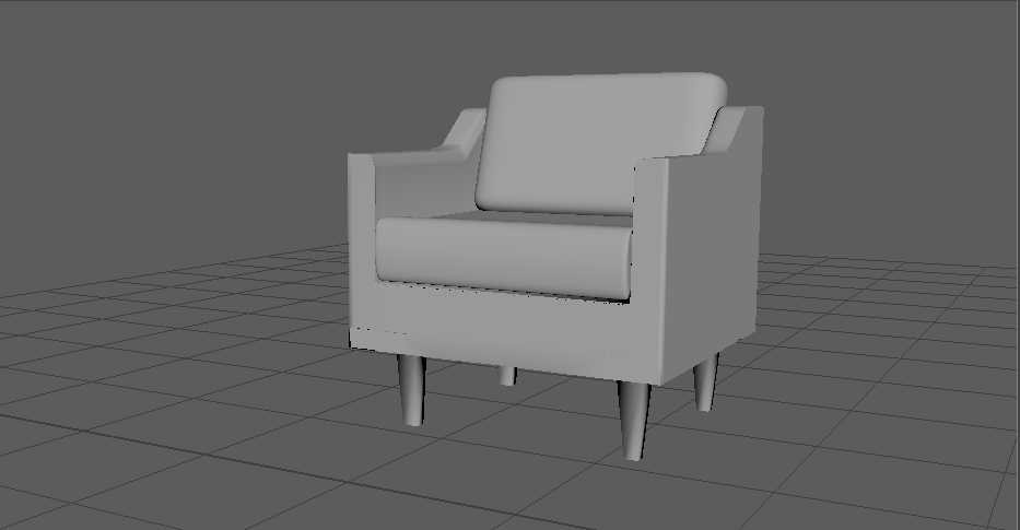
Problem statement: Modeling a chair using polygonal modelling tools.
Solution Description:In this exercise of modelling a chair, first I created cube with dimensions 6 x 2 x 6. Then using extrude tool, I created two sides and back side of chair. Here I curved and smooth the sides of chair using multicut and insert edge loop tools.
The chair cushions made smooth by using smooth tool. The front of sitting cushion made curve and smooth using insert edge loop tools, first I inserted multiple edge loops at front top of cushion and then adjusted each edge loop to make the front side smooth and curve. For legs of chair, first I selected four corner faces of bottom of chair and using bevel tool and extrude tool, I created chair legs. And finally the chair model finished.


CLASS EXERCISE 3
Problem statement: Creating detailed modelling of given hat
Solution description: In this exercise of modelling a hat, first I created cylinder using cylinder primitive. Here while creating cylinder, I subdivided cylinder height by 15 and width ()top and bottom) by 10. Then I selected vertices of top to make top of hat little curve. Using faces of top of cylinder, I make top of hat more smooth. Once top of hat part done, I selected bottom faces of cylinder and expand them , then using insert edge loop option, I created edge loop and by selecting all vertices of each edge, I partially made bottom part of hat. To make this part curve, I used smooth selection option and selected 4 to 5 side faces and edges and curve them. Like this step by step, I made bottom of hat curve. And finally complete hat model get created.
Link of maya file :
https://drive.google.com/open?id=0ByACdvkSx-3relF3ckwwT2ktak0


CLASS EXERCISE 1
Problem statement: Building a vehicle based on primitives (Scaling, translating and rotating)
Solution description: For this class exercise of building a vehicle, I built an airplane a kind of little fighter jet. I built this model of airplane in Maya 2017 using most of polygon primitives (sphere, cube, cone, cylinder, torus).
First I draw cylinder and stretch it to make shape of main body of airplane. I used cube for the wings of airplane, cone for the front part of airplane, sphere for the cockpit, and torus for the landing gear tyres of airplane.


PROJECT 1
Title (Problem Statement): Modeling an object (Car) using primitives
Date: 10/04/2017
Solution description: In this project of modelling an object using different primitives like polygon primitives, NURBS primitives etc. I modelled a car (racing car). For modelling car, I used polygon primitives : cube, cylinders, pipe, sphere, torus etc. for modelling different parts of car.
I followed the following steps/procedure for modelling car.
1. First I captured some pictures of car model through different angles: side, top, back, front etc. I referred these pictures in modelling car. I created 3 image planes and imported side, top, front view images of car in these image planes in maya.
2. Then I created polygon cube as basic body of car. Then I inserted multiple edge loops using insert edge loops tool. I also used multi cut tool for inserting small edges .
3. To create top part of car (Window, sitting area, bonnet), I adjusted control vertices, faces and edges of particular area of cube.
4. To make top part sitting area of car, I used extrude tool, I extruded surfaces and created box after that I cover this box by making window. I created window by creating surface on top by extruding one edge and then adjusted vertices.
5. To create side wing like structure, I extruded side edges to top curve surface and then adjusted it's vertices to make it look like real structure, then I make it little thick.
6. To create back part of car and lights, I created 2 torus and make their shape looks like back lights using lattice deformer . Then I connected them by extruding their edges, Finally I attached this structure to back part of car.
7. To create middle part of car, I used extrude tool, I extruded surface and make cubic structure then I insert edge loops and adjusted vertices and edges to make this structure looks like real structure. To smooth the edges, I used bevel tool.
8. Front part of car created using insert edge loops,extrude tool, adjusting edges , vertices.
9. The front side light of car created using cylinder and then attached it to main car body model.
10.Bottom part of car is a plane which is created by extrude tool.
11. Tyres of car created by polygon cylinder. I created the front and back tyres separately. For the tyres, I used extrude tool, I extruded surfaces of cylinder.
12. To connect these wheels together, I created pipe and attached the pipe to main car model. Then Attached Tyres to it. Like this, I attached front and back tyres to main car body.
13. After completing the whole model of car, I coloured the whole car. Some parts of car like tyres, middle engine part, back light part coloured in different colour.
Link to maya file:
https://drive.google.com/open?id=0Bx-YoHgqS_J1Nzh1NVUxX0JXYzA
Link to car model images :https://drive.google.com/open?id=0Bx-YoHgqS_J1eUFFd1JHRWJYN00


 Solar_1.PNG |  Solar_hypergraph1.PNG |
|---|